


Supporting structures and accessories
Supporting structures are steel made elements. They are essential addition to submersible mixers. The function of supporting structures is to keep a mixer in proper position during operation, and to enable mixer’s descending/lifting from the tank.
The following components can be marked out in our supporting structures: guide rail – backbone of the supporting structure; support buck – for mixer entrenching, it secures working position; sledge – connects mixer with guide rail; crane with hoisting winch – enables lifting/descending of mixer; assembly accessories: bases, brackets and others.
Supporting structures are suited for particular type of mixer. Each construction is available in rotational and stationary version. Our structures come in three basic material versions: made of stainless steel AISI 304, acid-proof steel AISI 316, galvanized carbon steel and others according to customer’s request.
All our supporting structures are attuned for exact tanks. On basis of tank’s geometry dimensions and information about technological processes, we can determine supporting structure length, optimal assembly way and installation spot.
If a supporting structure made by other manufacturer is already installed on site, on basis of its dimensions we can prepare modified sledge to be delivered with our mixer. In this way customer can make use of the old structure.
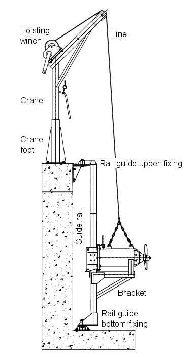
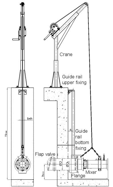
Drawing 1. Rotational supporting structure of type AN for AS mixers.
MODELS
Supporting structures of type AN – purposed for submersible mixers of type AS and AR; the mixer moves along single, of square cross-section, guide. Mixer is secured in working position by means of bucket. There are two versions available: rotational and stationary. Our supporting structures are made of the following materials: galvanized steel, stainless steel AISI 304, acid-proof steel AISI 316.
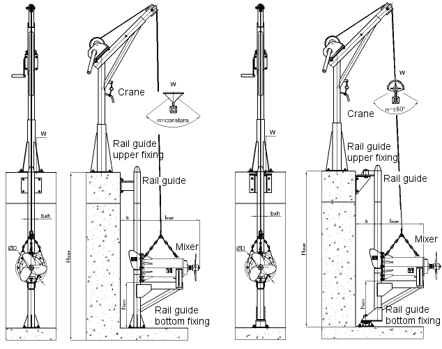
Drawing 2. Supporting structure of type AN, stationary (to the left) and rotational (to the right) versions.
| SUPPORTING STRUCTURES AN | ||||||
| Model | S [mm] | Hmax* [mm] | hmin [mm] | d [mm] | Crane | |
| α = ±60° | α = const. | |||||
| AN60 | 60 x 60 | 6000 | 500 | 255 | 180 | ZS15 |
| AN80 | 80 x 80 | 6000 | 600 | 265 | 200 | ZS15 |
| AN100 | 100 x 100 | 6000 | 900 | 265 | 200 | ZS25 |
| AN120 | 120 x 120 | 6000 | 1500 | 265 | 200 | ZS40 |
Description:
S – guide’s cross-section
Hmax – maximum tanks’ depth (* it’s possible to use longer structures if only additional bracket is used)
hmin – minimum distance between the bottom of the tank and the mixer
d – the distance between guide rail axis and wall of the tank for rotational structures featured with changeable α and for stationary structures featured with constant α
Supporting structures of type AW – purposed for submersible mixers of type AS and AR; the mixer moves along single, of round cross-section, guide. Mixer is secured in working position by means of bucket. Our supporting structures are made of the following materials: galvanized steel, stainless steel AISI 304, acid-proof steel AISI 316.
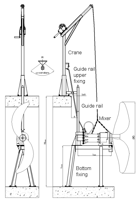
Drawing 3. Supporting structure of type AW.
| SUPPORTING STRUCTURES AW | ||||||
| Model | S [mm] | Hmax* [mm] | hmin | d [mm] |
Crane | |
| For propellers of diameter [mm] | Value of hmin [mm] | |||||
| AW50 | 50 x 50 | 6000 | 480 – 800 900 – 1200 |
625 825 |
255 | ZS15 |
| AW60 | 60 x 60 | 6000 | 1200 – 2000 2200 – 2500 |
1140 1500 |
265 | ZS15 |
Description:
S – guide’s cross-section
Hmax – maximum tanks’ depth (* it’s possible to use longer structures if only additional bracket is used)
hmin – minimum distance between the bottom of the tank and the mixer
d – the distance between guide rail axis and wall of the tank
Supporting structures of type AD – purposed for submersible mixers of type AR; the mixer moves along two guides of round cross-section, guide. Mixer is secured in working position by means of bucket. Our supporting structures are made of the following materials: galvanized steel, stainless steel AISI 304, acid-proof steel AISI 316.
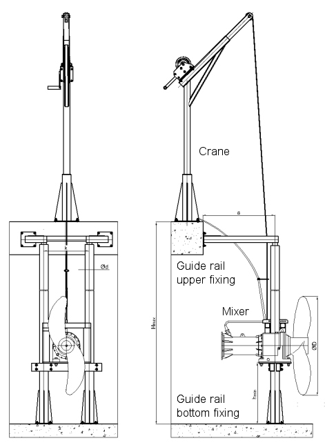
Drawing 4. Supporting structure of type AD.
| SUPPORTING STRUCTURE AD | |||||||
| Model | Φ [mm] | Hmax* [mm] | hmin | l [mm] | D [mm] |
Crane | |
| For propellers of diameter [mm] | Value of hmin [mm] | ||||||
| AD | 108 | 6000 | 900 – 1200 1500 – 2000 2200 – 2500 |
850 1250 1500 |
552 | 875 | ZS25, ZS40 |
Description:
φ – diameter of round cross-section guide rail
Hmax – maximum tanks’ depth (* it’s possible to use longer structures if only additional bracket is used)
hmin – minimum distance between the bottom of the tank and the mixer
l – guide rails astride
d – the distance between guide rail axis and wall of the tank
Supporting structures of type ANP – purposed for pumping mixers of type PAS and PAR; the mixer is connected with guide rail of square cross-section by means of special handling, which is an integral part of mixer’s pumping ring. In working position mixer is entrenched to the pipeline. Our supporting structures are made of the following materials: galvanized steel, stainless steel AISI 304, acid-proof steel AISI 316.
Drawing 5. Supporting structure of type ANP.
| SUPPORTING STRUCTURE ANP | |||||
| Model | S [mm] | Hmax* [mm] | hmin [mm] | d [mm] |
Crane |
| ANP60 | 60 x 60 | 6000 | 400 | 180 | ZS25 |
| ANP80 | 80 x 80 | 6000 | 0,5 x φd + 300 | 180 | ZS25, ZS40 |
Description:
S – guide rail diameter
Hmax – maximum tanks’ depth (* it’s possible to use longer structures if only additional bracket is used)
hmin – minimum distance between the bottom of the tank and the mixer
d – the distance between guide rail axis and wall of the tank
Crane with hoisting winch – purposed for lifting/descending mixer along the guide rail. Available as standalone version and version integrated with the structure. Our cranes are made of the following materials: galvanized steel, stainless steel AISI 304, acid-proof steel AISI 316.
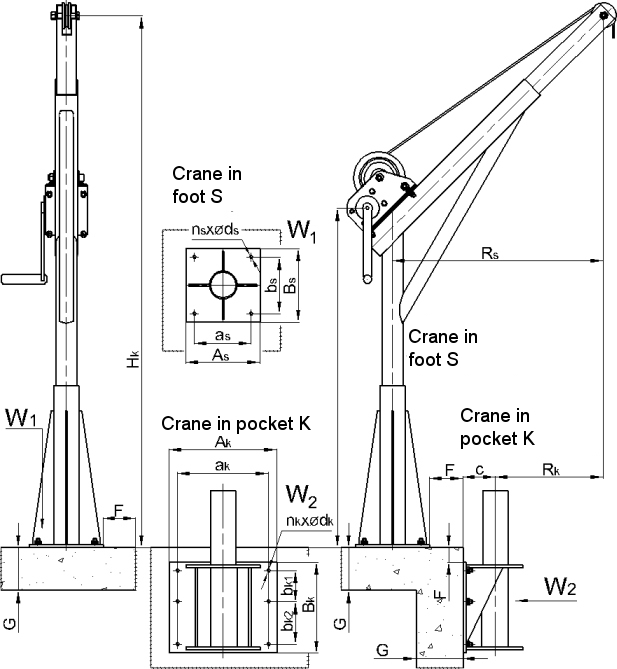
Drawing 6. Crane of type ZS.
| CRANES | |||
| Model | Capacity [kg] | Fixing | |
| Foot | |||
| ZS15 | 150 | Yes | Yes |
| ZS25 | 250 | Yes | Yes |
| ZS40 | 400 | Yes | Yes |
DOWNLOAD
![]() - Supporting structure AN60
- Supporting structure AN60
![]() - Supporting structure AN80
- Supporting structure AN80
![]() - Supporting structure AN100
- Supporting structure AN100
![]() - Supporting structure AW60
- Supporting structure AW60
![]() - Supporting structure AD
- Supporting structure AD
![]() - Supporting structure ANP60
- Supporting structure ANP60
![]() - Supporting structure ANP80
- Supporting structure ANP80
![]() - Cranes ZS15, ZS25, ZS40
- Cranes ZS15, ZS25, ZS40
![]() - Fixing options – ZS and AN
- Fixing options – ZS and AN
![]() - Fixing options – ZS and AW
- Fixing options – ZS and AW
![]() - Fixing options – ZS and AD
- Fixing options – ZS and AD
![]() - Fixing options – ZS and ANP
- Fixing options – ZS and ANP
![]() - Flange dimensions – ANP
- Flange dimensions – ANP